Apple ][e
![Apple ][e](/img/apple2e/cover.jpg "Cover Image")
CHAPTER 1: INTRODUCTION
Being quite critical of today’s Apple products (even very critical, Grrrrr), I nevertheless jumped at the chance (I should not have missed this opportunity) and acquired an Apple ][e. And I can say that I am quite amazed by the quality of assembly and especially the design of the printed circuits.
It’s the first time I see this kind of letter + number grid printed on all the printed circuits.
This time, the problem was known in advance. The previous owner, who also sold me the IBM PC a few months ago, told me that the floppy drive was not working. At the price he sold it to me, this was not a big problem, at least in perspective.
First of all, let’s take a look at the machine. It’s a set including the case (computer + keyboard) as well as the green monochrome screen.
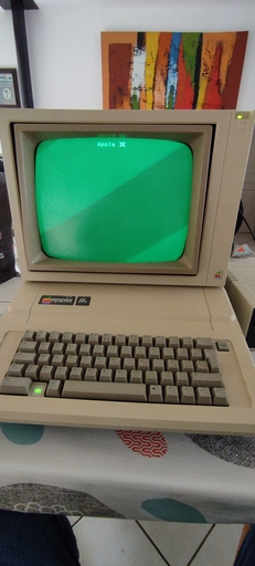
The two elements are connected with a simple RCA cable that delivers a composite signal from the motherboard to the screen.
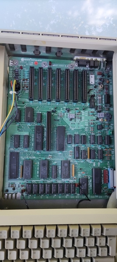
Under the trap door (easily removable, a big point for Apple) we find the whole motherboard as well as the different slots for the daughterboards (to connect printers, floppy drives, modems, graphic cards), as well as an extension port to add extra features to the system (80 columns card, buffer).
CHAPTER 2 : The floppy disk drive
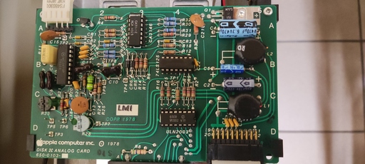
The APPLE ][e does not have a built-in floppy disk controller. All peripherals (except the cassette drive) must communicate with the processor via a daughter board. Here the DISK][ drives must be connected to the DISK][ card.
This card has two EPROMs allowing communication between the readers and the processor. In short, they translate the language of the machine into floppy language and vice versa. And it supplies the drives with the different necessary voltages (+5, +12 and -12V)
On this card, we can connect two floppy drives. Only drive 1 is used at startup. This can be changed, but only by modifying the EPROM code (it indicates which drive is the primary and which is the secondary).
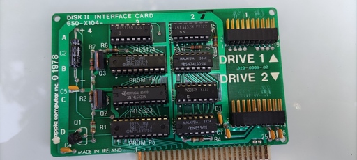
The selection of the reader is done in a simple way. The EPROM will send a signal to the drive it wants to use. All other signals are connected in parallel to the EPROM.
The choice to have used analog components for the floppy drives allows a simplified management of the different drives by the system, but also a reduced cost at the production level.
CHAPTER 3: Finding the problem
The previous owner had told me about the problem and specified that, if the player is plugged on the port N°2, it seems to work.
So I plugged the player on the port N°2 and indeed, it runs. Of course I could not start any program on it, because the software is made to boot on the reader 1. However, it runs too much, it never stops. And above all, the fact that it runs indicates that the EPROM has activated drive 2 (logically).
I unplug the drive and look at the voltages at the terminals of each power supply pin of the DISK][ card. Everything is OK. As I don’t have an oscilloscope at the moment, I can’t analyze the other signals coming out of the card.
So I remove the card from its slot to make a visual inspection of the capacitors. And there I have the impression, by touch, that one of the integrated circuits is hot. I look at its datasheet and it is an 8 bits shift register (DM9334).
With the help of the CEM de Ronchin I was able to recover a part of the integrated circuits of the board. We then tested them one by one with cLx to check if they are fully functional. Unfortunately it was too late to realize that the DM9334 had another denomination in 74LSxxx (74LS259).
The next day, I removed all the ICs from the board (those with a replacement) to put aside the hypothesis of a IC out of order, but it was not conclusive. The reader does not start at startup and on port N°2 it always runs without stopping.
The EPROMs are doing their job correctly. It had to fall on the DM9334. If we look closely at the relations between the different ICs it is indeed the DM9334 which “activates” the floppy drive.
CHAPTER 4: Katastrophe!

Deep breath
One of the problems with this kind of connector is that it’s easy to shift the pins by one notch. And in this case, I had to do it correctly.
I didn’t shift the pins to the right or to the left, no that’s too easy, I shifted the pins forward!
So I injected a voltage on the logical pins of the floppy drive. flip the table
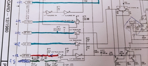
Here is the pin layout on the computer side (find it HERE)
| 1 | 3 | 5 | 7 | 9 | 11 | 13 | 15 | 17 | 19 |
|---|---|---|---|---|---|---|---|---|---|
| GND | GND | GND | GND | -12 | +5 | +12 | +12 | +12 | +12 |
| 00 | 01 | 02 | 03 | WR REQ | +5 | !ENBL | RD DATA | WR DATA | W PROT |
| 2 | 4 | 6 | 8 | 10 | 12 | 14 | 16 | 18 | 20 |
This give an idea of what happened :
- WR REQ took -12V
- !ENBL took +12V
- RD DATA took +12V
- WR DATA took +12V
- W PROT took +12V
And of course, a burning smell and the Apple ][e which started looping as it was shorted.
The player controller board here is now cooked and ready to be eaten:
The days go by with this remorse of not having checked the connections before lighting.
CHAPTER 5 : A glimmer of hope
Going back to the CEM de Ronchin, I could get my hands on a DM9334 printed circuit board, finally, in its 74LS259 version.
So we can test the whole Apple Disk][ board with working integrated circuits.
I leave the drive plugged on port N°2 expecting it to be activated when the computer starts, but by miracle, it does not start. We then hurry to turn off everything and plug the player on the port N°1 and at the startup, the player is activated!
Immense joy and happiness around the beast which undergoes its operation with open heart.
The joy will be short-lived due to the fact that the control card took a blow and the diskettes do not load. But finally it is a great advance in the understanding of the Apple Disk][] card.
Now I have to fix my mistakes…
CHAPTER 6 : Awwww shit, here we go again
(In progress)
Thanks
Thanks to :
- cLx for its multiple hours spent together to get migraines.
- CEM de Ronchin for their welcome, the loan of material and their precious help.